electromagnetic water flow meter working principle
sales01@cxflowmeter.com
WhatsApp: 008618049841995
Electromagnetic
Water Flow Meter Working Principle
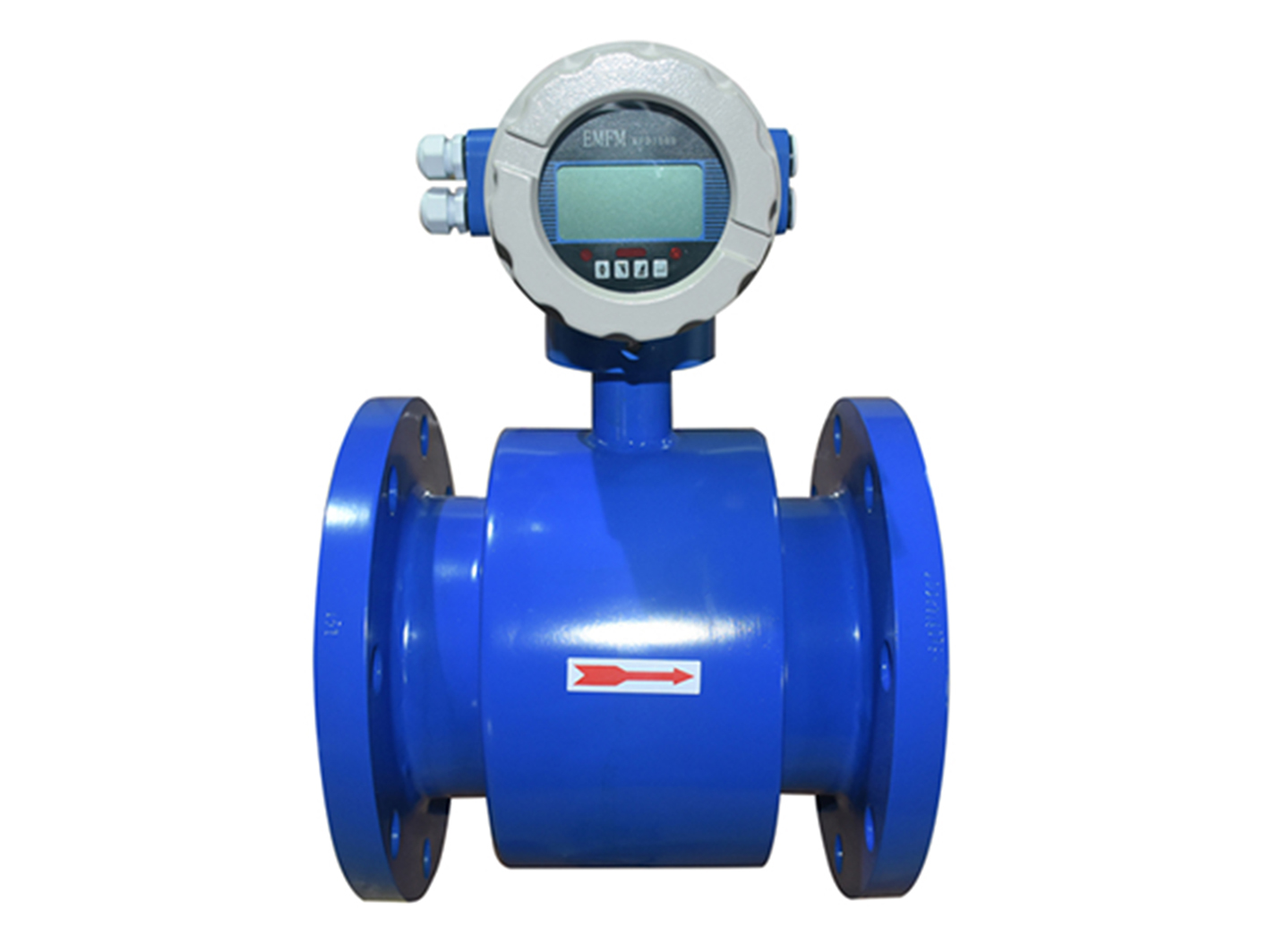
An electromagnetic water flow meter (EMF) is a high-precision flow measurement instrument designed based on Faraday's law of electromagnetic induction. It is specifically used to measure the volume flow of conductive liquids (such as water, sewage, and acid-base solutions). Its core principle is to use a magnetic field to induce the electromotive force generated by the flowing conductive liquid, thereby inferring the flow rate. The following is a detailed explanation of its working principle:
1. Core Principle: Faraday's Law of Electromagnetic Induction
When a conductive liquid flows perpendicularly in a magnetic field, it cuts the magnetic flux lines, generating an induced electromotive force (voltage) in the liquid that is proportional to the flow rate. The mathematical expression is:
E=k⋅B⋅v⋅D
E
: Induced electromotive force (voltage, unit: volts V)
k
: Meter constant (related to structural parameters such as electrode spacing and pipe diameter)
B
: Magnetic field strength (unit: Tesla T)
v
: Average liquid velocity (unit: meters per second m/s)
D
: Pipe inner diameter (unit: meters m)
Key conclusion: The induced electromotive force
E
is proportional to the liquid flow velocity
v
. Therefore, by measuring
E
, the flow velocity and, therefore, the flow rate can be inferred.
II. Working Process Detailed Explanation
Magnetic Field Generation
The electromagnetic flowmeter sensor contains an excitation coil. When energized, it generates a uniform magnetic field perpendicular to the pipe axis.
The direction of the magnetic field is typically perpendicular to the direction of liquid flow, ensuring that the liquid cuts the magnetic flux lines.
Electromotive force induction
When a conductive liquid flows through a magnetic field, the positive and negative ions in the liquid are deflected by the Lorentz force, accumulating charges on the electrodes on both sides of the pipe, generating an induced electromotive force. The direction of the electromotive force is perpendicular to the magnetic field and the flow direction (right-hand rule).
Signal Acquisition and Processing
The electrodes convert the induced electromotive force E
into an electrical signal and transmit it to the transmitter.
The transmitter amplifies, filters, and linearizes the signal to eliminate interference (such as power frequency noise and fluid electrochemical noise).
The volume flow rate Q
is calculated according to the formula Q = A⋅v
(A
is the pipe cross-sectional area) and outputs a standard signal (such as 4-20mA, pulse, RS485, etc.).
III. Structural Components
Sensor (Measuring Tube)
Pipeline: Non-magnetic material (such as stainless steel, plastic) to ensure magnetic field penetration.
Lining: The inner wall is covered with an insulating material (such as rubber, polytetrafluoroethylene) to prevent short circuits and accommodate corrosive media.
Electrodes: Installed in pairs, in direct contact with the liquid to sense the electromotive force. The material must be corrosion-resistant (such as stainless steel, Hastelloy).
Excitation Coil: Generates a stable magnetic field, typically using a low-frequency rectangular wave excitation to reduce interference. Transmitter (Converter)
Signal Processing Circuit: Amplifies weak EMF signals and suppresses noise.
Microprocessor: Calculates flow rate, performs temperature compensation, and performs empty pipe detection.
Display and Output Module: Displays flow rate values and outputs analog/digital signals.
IV. Technical Features and Advantages
High Accuracy and Stability
Measurement accuracy reaches ±0.5%, with excellent long-term stability and minimal impact on fluid density, viscosity, temperature, and pressure.
No moving parts, resulting in minimal wear and long service life.
Wide Turndown Ratio
With a turndown ratio of up to 100:1, it is suitable for measuring low to high flow rates.
Bidirectional Measurement
Capable of detecting forward or reverse flow, it is suitable for complex piping systems.
Low Pressure Loss
No obstructions in the pipeline, resulting in minimal pressure loss and reduced pumping energy.
High Adaptability
Capable of measuring corrosive liquids and those containing solid particles (such as sewage and slurries), but requires the selection of appropriate lining and electrode materials.
V. Application Scenarios
Municipal Water Supply and Drainage: Monitoring water flow rates at waterworks and sewage treatment plants.
Industrial Process Control: Measuring liquid batching and circulating water flow in the chemical, papermaking, and food industries.
Agricultural Irrigation: Optimizing irrigation water usage and improving water resource utilization.
Environmental Monitoring: Monitoring water flow in rivers and lakes, and measuring pollution emissions.
Energy: Measuring cooling water flow and balancing thermal networks.
VI. Limitations and Precautions
Conductivity Requirements: Liquid conductivity must be ≥ 5 μS/cm (pure water is not applicable; electrolytes must be added).
Non-conductive media (such as oil and gas) cannot be measured.
Installation Requirements: Full pipe installation is required to avoid air accumulation and measurement errors.
Avoid strong electromagnetic interference sources (such as high-power motors and inverters).
The straight pipe length must meet the requirements (typically 5D in front and 3D in the back, where D is the pipe diameter).
Maintenance Requirements: Regularly check the electrode for contamination and clean the lining surface. Avoid lining wear or electrode corrosion, as this will require sensor replacement.
WhatsApp: 008618049841995